
Optical surface quality describes visible defects on a polished optical surface, such as scratches and digs. It is commonly specified using two numbers separated by a dash, such as 60-40, 40-20 or 20-10.
In the MIL-PRF-13830 scratch-dig convention, the first number is a visual scratch grade and the second number limits dig size. Lower numbers indicate a tighter requirement, but the two numbers are evaluated differently: scratches are compared with reference standards, while digs are dimensionally measured.
For many commercial imaging components, 60-40 is sufficient. Precision instruments and low-to-moderate-power laser systems commonly use 40-20. High-precision or demanding laser applications may require 20-10 or better.
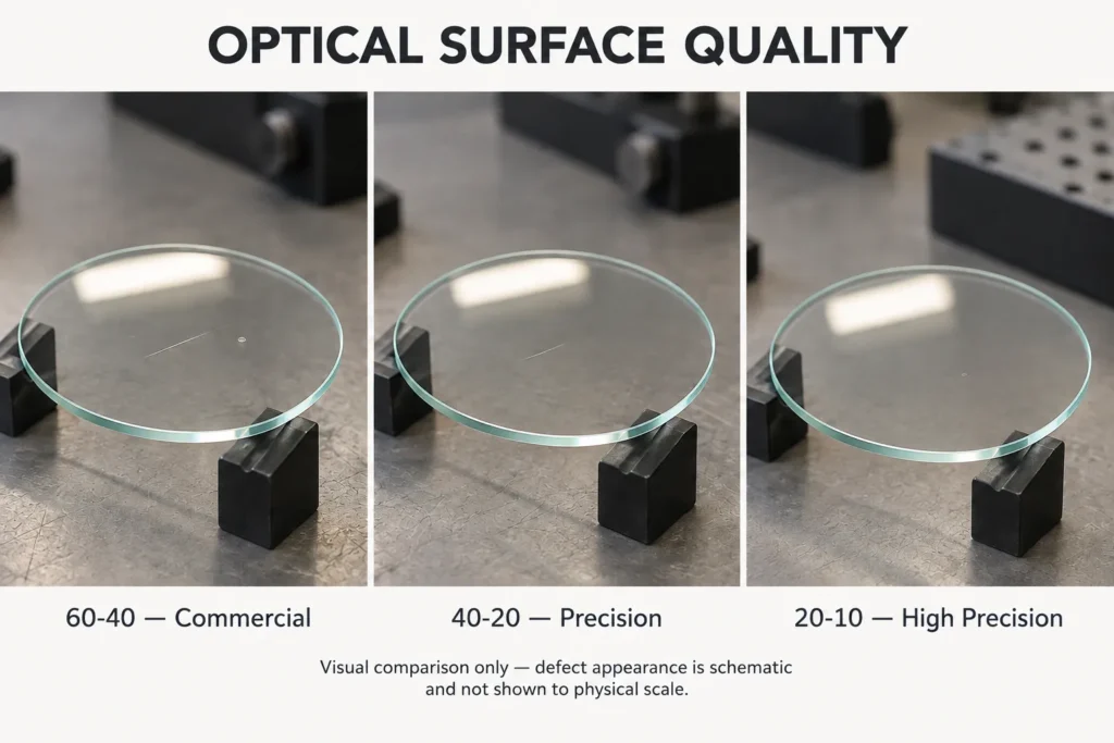 60-40 vs 40-20 vs 20-10 Optical Surface Quality
In This Guide
Quick Answer: Which Surface Quality Should You Choose?
Choose 60-40 for general commercial optics, protective windows and imaging systems where minor cosmetic defects are unlikely to materially affect system performance.
Choose 40-20 for precision imaging, scientific instruments and many low-to-moderate-power laser applications.
Choose 20-10 for high-precision optics, small focused beams and demanding laser systems where surface defects may increase scatter or reduce performance.
Do not specify 20-10 automatically. Tighter surface-quality requirements can increase manufacturing difficulty, inspection time, cost and lead time.
Important: Scratch-dig describes visible surface imperfections. It does not replace specifications for surface roughness, surface flatness, transmitted wavefront, coating quality or laser-induced damage threshold.
What Does Scratch-Dig Mean?
A scratch-dig specification contains two numbers:
Scratch number – Dig number
For example, in a 40-20 specification:
40is the maximum allowable scratch comparison grade; an observed scratch must not appear brighter than the approved Scratch 40 reference.20is the maximum individual dig designation, subject to the standard’s additional quantity and spacing limits.
Under the traditional MIL-PRF-13830 scratch-dig system, scratches are evaluated visually by comparison with calibrated reference standards under controlled lighting.
The scratch number should not be treated as a direct physical scratch-width measurement. It is primarily a visibility comparison against a reference standard.
Under the MIL-PRF-13830 convention, the dig number has a dimensional relationship: it is the diameter of the largest permitted individual dig expressed in units of 0.01 mm. Additional limits on the total number, spacing and distribution of digs also apply:
- Dig 40 corresponds to 0.40 mm
- Dig 20 corresponds to 0.20 mm
- Dig 10 corresponds to 0.10 mm
Acceptance also depends on the number, location and distribution of defects—not only the largest individual imperfection.
60-40 vs 40-20 vs 20-10
| Surface quality |
Scratch requirement | Maximum individual dig diameter |
Typical use |
|---|---|---|---|
| 60-40 | Compared with Scratch 60 reference standard | 0.40 mm | Commercial optics and general imaging |
| 40-20 | Compared with Scratch 40 reference standard | 0.20 mm | Precision instruments and many laser systems |
| 20-10 | Compared with Scratch 20 reference standard | 0.10 mm | High-precision and demanding laser optics |
Note: This table is a preliminary guide based on MIL-style scratch-dig terminology. Final acceptance depends on the specified standard, inspection conditions, clear aperture, defect length, quantity, spacing and distribution requirements.
What Is 60-40 Surface Quality?
60-40 is a common and economical specification for commercial optical components.
It is often suitable for:
- Protective optical windows
- General imaging lenses
- Machine-vision systems
- Illumination optics
- Industrial sensors
- Prototypes and laboratory systems
Small cosmetic defects may be visible during inspection, but they may have little measurable effect on ordinary imaging or illumination performance.
A 60-40 requirement is often more practical than a tighter grade when the optic is not near a focal plane and the system is not sensitive to scattered light.
What Is 40-20 Surface Quality?
40-20 is a precision-grade specification used when surface appearance and scattered light are more important.
Typical applications include:
- Scientific instruments
- Precision imaging systems
- Low-to-moderate-power laser optics
- Beam-delivery systems
- Spectroscopy components
- Smaller optical elements
Compared with 60-40, a 40-20 requirement allows less visible scratching and smaller digs.
It normally involves additional polishing control, cleaning, handling and inspection, which can increase manufacturing cost.
What Is 20-10 Surface Quality?
20-10 is a high-precision surface-quality specification.
It may be selected for:
- High-precision laser optics
- Small focused beams
- High-energy-density regions
- Sensitive scattering measurements
- High-contrast imaging
- Critical scientific systems
A tighter scratch-dig grade can reduce the risk of scattering from visible surface defects. However, it does not by itself guarantee a high laser damage threshold.
Laser performance also depends on substrate purity, subsurface damage, surface roughness, cleanliness, coating defects, absorption and the laser parameters.
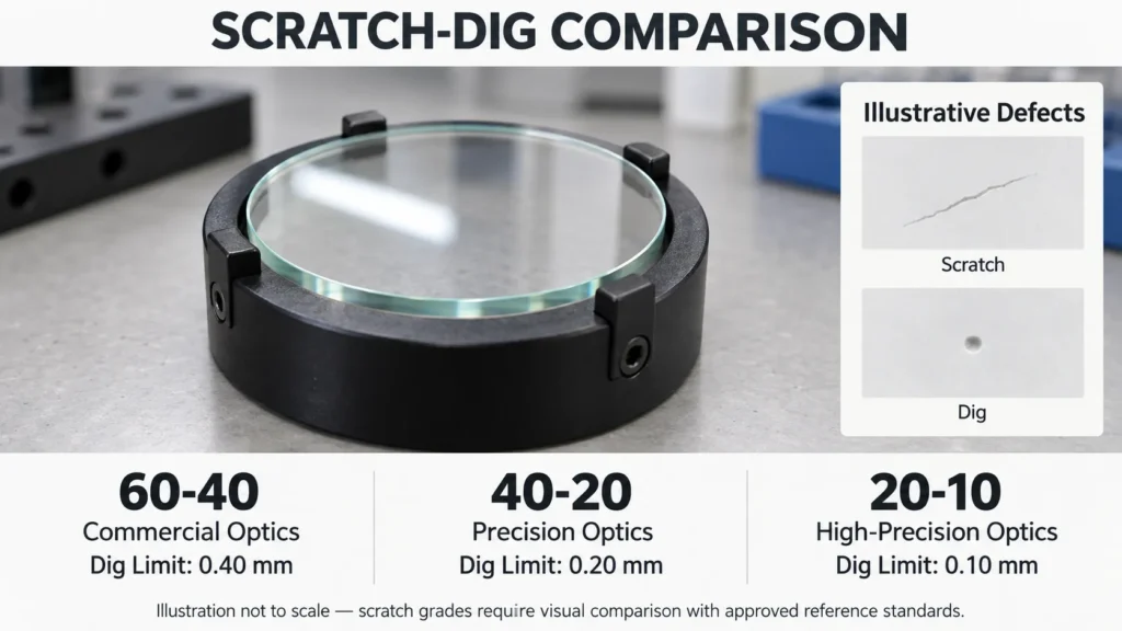 Scratch-Dig Comparison for Common Optical Surface Quality Grades
How Is Surface Quality Inspected?
Traditional scratch-dig inspection is generally performed under controlled lighting by comparing the optical surface with approved reference standards.
The inspector evaluates:
- Scratch visibility
- Dig diameter
- Defect length
- Number of defects
- Defect distribution
- Location within the clear aperture
Inspection results can be influenced by lighting, viewing geometry, magnification, cleanliness and inspector experience.
The drawing or purchase order should identify the applicable standard. A requirement written only as “40-20” may be incomplete if the customer and manufacturer use different inspection systems.
For critical optics, both parties should agree on:
- Inspection standard
- Lighting conditions
- Reference standard
- Magnification, if applicable
- Clear aperture
- Acceptance zones
- Inspection report requirements
How Does Surface Quality Affect Optical Performance?
Scratches and digs can scatter light away from the intended optical path.
Their impact depends on:
- Defect size and depth
- Defect location
- Wavelength
- Beam diameter
- Optical power density
- Position relative to an image or focal plane
- Detector sensitivity
- Required contrast
A small defect near a focal plane may be more noticeable than the same defect on a large window far from focus.
For many commercial imaging systems, 60-40 provides acceptable performance. Specifying 20-10 without a system-level reason may add cost without producing a meaningful improvement.
What Scratch-Dig Does Not Specify
Scratch-dig should not be confused with other optical requirements.
Surface Roughness
Surface roughness describes microscopic texture, normally measured in nanometers. A surface can meet a tight scratch-dig requirement and still have unsuitable roughness.
Surface Flatness or Figure
Flatness and surface figure describe deviation from the intended optical shape. They are commonly specified in waves or as physical form error.
Transmitted Wavefront
Transmitted wavefront error describes how the finished optic changes the wavefront passing through it.
Coating Quality
A substrate may meet the required scratch-dig grade before coating but develop coating defects, pinholes or handling damage afterward. Final inspection conditions should be stated.
Laser Damage Threshold
Scratch-dig alone does not define laser-induced damage threshold. Laser wavelength, pulse duration, repetition rate, beam size, coating and test method must be specified separately.
How to Choose the Right Surface Quality
Use the following practical approach:
- Identify whether the optic is used for imaging, illumination, sensing or laser transmission.
- Determine the beam diameter and position of the optic.
- Evaluate whether scattered light or cosmetic appearance is critical.
- Review the laser power density, if applicable.
- Select the least restrictive grade that meets the real performance requirement.
- Confirm the inspection standard and clear aperture with the manufacturer.
A typical starting point is:
- 60-40 for commercial optics
- 40-20 for precision optics
- 20-10 for demanding laser or high-precision systems
These are general guidelines rather than universal rules.
Common Specification Mistakes
Treating the Scratch Number as a Physical Width
Under the traditional comparator-based system, the scratch number is a visual grade rather than a direct micron measurement.
Ignoring Defect Quantity and Distribution
Passing the maximum individual defect size does not automatically mean the entire surface is acceptable.
Omitting the Inspection Standard
MIL-style scratch-dig and ISO surface-imperfection specifications are not automatically interchangeable.
Using Scratch-Dig to Specify Roughness
Scratch-dig describes visible defects. Surface roughness requires a separate numerical specification and measurement method.
Automatically Selecting 20-10
Tighter requirements increase cost and may not improve the actual system performance.
Frequently Asked Questions
Is 40-20 Better Than 60-40?
A 40-20 specification is tighter than 60-40 under the same referenced standard and inspection conditions: scratches must meet a lower visibility grade and digs are smaller. Whether that tighter requirement improves system performance depends on the application.
What Does the Dig Number Mean?
Under the MIL-PRF-13830 convention, the dig number represents diameter in units of 0.01 mm. Dig 20 corresponds to a maximum individual diameter of 0.20 mm, with additional quantity and spacing limits defined by the standard.
Does 20-10 Guarantee Better Laser Performance?
No. It can reduce visible defects, but laser performance also depends on roughness, cleanliness, absorption, coating quality, subsurface damage and laser conditions.
Is Scratch-Dig the Same as Surface Roughness?
No. Scratch-dig describes visible localized defects, while roughness describes microscopic surface texture.
Can MIL Scratch-Dig Be Directly Converted to ISO 10110?
Not reliably as a simple one-to-one conversion. The systems use different definitions and inspection approaches. The required standard should be stated explicitly.
Custom Optical Components from Chenyu Optics
Chenyu Optics manufactures custom optical windows, lenses, mirrors, prisms and other precision optical components.
Components can be evaluated according to:
- Optical material and grade
- Operating wavelength
- Dimensions and tolerances
- Surface quality
- Surface roughness
- Surface flatness or figure
- Transmitted wavefront
- Clear aperture
- Optical coating
- Laser requirements
- Inspection and documentation requirements
- Prototype or production quantity
Final specifications should be confirmed according to the customer drawing, application, referenced inspection standard and available measurement method.
Need Help Specifying Optical Surface Quality?
Send us your optical drawing, application, wavelength, component dimensions, laser conditions and inspection requirements.
Chenyu Optics can help determine whether 60-40, 40-20, 20-10 or another surface-quality grade is appropriate for your component.