
Bandpass optical filters transmit a selected wavelength band while blocking wavelengths outside that band. Three specifications frequently used to describe their performance are optical density, full width at half maximum and center wavelength.
These values are often written as OD, FWHM and CWL. Each describes a different part of the spectral response. A complete filter specification should also define the blocking range, peak transmission, angle of incidence, polarization and operating temperature.
 Bandpass Filter OD FWHM and CWL
In This Guide
Quick Answer
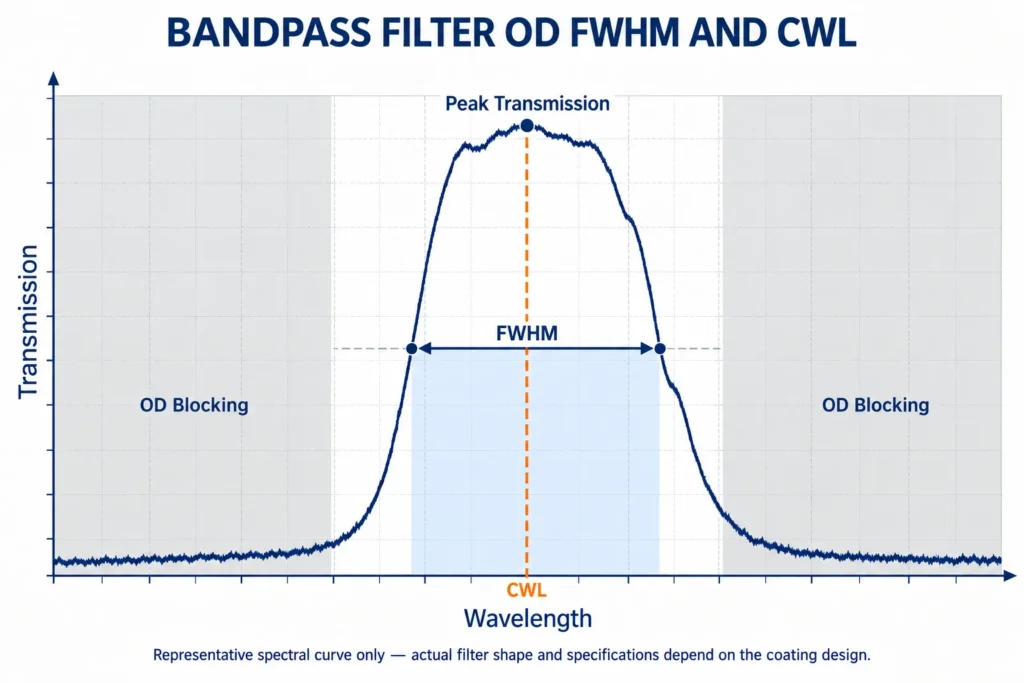
CWL, or center wavelength, identifies the approximate center of the transmission band.
FWHM, or full width at half maximum, describes the bandwidth measured between the two wavelengths where transmission falls to half of the peak value.
OD, or optical density, describes how strongly unwanted wavelengths are blocked:
OD = −log₁₀(T)
Where T is the transmission expressed as a decimal.
Examples:
- OD 2 = 1% transmission
- OD 3 = 0.1% transmission
- OD 4 = 0.01% transmission
- OD 5 = 0.001% transmission
An OD value is incomplete unless the wavelength range over which it applies is also specified.
What Is a Bandpass Filter?
A bandpass filter transmits light within a selected wavelength interval and blocks wavelengths below and above that interval.
Typical applications include:
- Fluorescence imaging
- Spectroscopy
- Machine vision
- Laser-line isolation
- Medical instruments
- Environmental sensing
- Astronomy
- Multispectral imaging
- Detector protection
Most precision bandpass filters use multilayer thin-film coatings. The coating design creates constructive interference in the passband and suppresses light in the blocking regions.
The finished spectrum depends on the substrate, coating materials, layer design, angle of incidence and polarization.
What Is Center Wavelength?
Center wavelength identifies the nominal central position of the passband.
It is commonly abbreviated as CWL and expressed in nanometers or micrometers.
For a band defined by two wavelengths at 50% of the peak transmission, one common CWL definition is:
CWL = (λ₁ + λ₂) ÷ 2
Where:
- λ₁ = lower half-maximum wavelength
- λ₂ = upper half-maximum wavelength
For example, if the half-maximum points occur at 495 nm and 505 nm:
CWL = (495 + 505) ÷ 2 = 500 nm
The filter would therefore have a nominal CWL of 500 nm.
This midpoint definition is common, but manufacturer conventions can differ for asymmetric, flat-top or irregular passbands. The drawing or datasheet should state the CWL definition and measurement conditions.
CWL Tolerance
A custom filter specification normally includes both a nominal CWL and a tolerance.
For example:
CWL: 500 nm ±2 nm
A tighter tolerance can require additional coating control, spectral measurement and production sorting.
The necessary tolerance depends on:
- Source wavelength
- Detector sensitivity
- Target spectral feature
- FWHM
- Angle of incidence
- Operating temperature
- Permitted system variation
A ±1 nm tolerance may be important for a narrow laser-line filter but unnecessary for a broad machine-vision filter.
What Is FWHM?
FWHM means full width at half maximum.
It measures the passband width between the wavelengths where transmission is 50% of the filter’s peak transmission.
The calculation is:
FWHM = λ₂ − λ₁
Using the previous example:
- Lower half-maximum wavelength: 495 nm
- Upper half-maximum wavelength: 505 nm
Therefore:
FWHM = 505 − 495 = 10 nm
The filter can be described as:
CWL 500 nm
FWHM 10 nm
FWHM describes bandwidth, but it does not fully describe the filter shape. Two filters can have the same CWL and FWHM but different peak transmission, edge steepness and out-of-band blocking.
Narrow vs Broad FWHM
A narrow FWHM passes a smaller wavelength interval. This can improve spectral isolation but may also make the system more sensitive to:
- CWL tolerance
- Angle of incidence
- Temperature
- Source wavelength drift
- Manufacturing variation
- Polarization effects
A broader FWHM accepts more wavelength variation and may provide higher total signal, but it allows more background light to reach the detector.
The best bandwidth depends on the balance between signal level and spectral selectivity.
What Is Optical Density?
Optical density describes the attenuation of unwanted light.
The equation is:
OD = −log₁₀(T)
Where transmission must be entered as a decimal.
For example, if transmission is 0.0001:
OD = −log₁₀(0.0001) = 4
The blocking level is therefore OD 4.
Optical density is logarithmic. Increasing from OD 3 to OD 4 reduces transmitted unwanted light by another factor of ten.
OD requirements should also state whether the value is average or absolute. For example, ODavg ≥4 means the average blocking over the stated range must meet OD 4, while an absolute OD ≥4 requirement means every specified wavelength in that range must meet the limit.
OD and Transmission Comparison
| Optical Density | Transmission Corresponding to OD | Approximate Attenuation | Typical Meaning |
|---|---|---|---|
| OD 1 | 10% | 10× | Limited blocking |
| OD 2 | 1% | 100× | Moderate blocking |
| OD 3 | 0.1% | 1,000× | Strong blocking |
| OD 4 | 0.01% | 10,000× | Very strong blocking |
| OD 5 | 0.001% | 100,000× | Demanding blocking |
| OD 6 | 0.0001% | 1,000,000× | Specialized high blocking |
These values show the mathematical relationship between OD and transmission. Practical filter performance also depends on measurement noise, spectral range, coating design and stray light.
High-OD verification is limited by the spectrophotometer noise floor, stray light, spectral bandwidth and dynamic range. An OD 6 requirement may need a dedicated blocking scan or another specialized measurement method, so the verification method should be agreed before production.
Why Must the Blocking Range Be Specified?
Writing only OD 4 is incomplete.
The specification should identify the wavelength interval where OD 4 is required, for example:
Blocking: OD ≥4 from 350–450 nm and 550–1000 nm
The blocking range affects coating-stack thickness, manufacturing complexity, verification difficulty and cost.
Extending high blocking over a very broad wavelength range can be substantially more difficult than blocking only a limited region around the passband.
The blocking range should cover wavelengths that could reach the detector and interfere with the measurement. It does not need to include regions where the source emits no meaningful energy or where the detector has no sensitivity.
How CWL FWHM and OD Work Together
Consider a filter specified as:
- CWL: 500 nm ±2 nm
- FWHM: 10 nm ±2 nm
- Peak transmission: ≥85%
- Blocking: OD ≥4 from 350–450 nm and 550–1000 nm
This specification describes:
- Where the passband is located
- How wide the passband is
- How much desired light passes through
- How strongly unwanted wavelengths are suppressed
- Where the blocking requirement applies
Removing any one of these items leaves an incomplete description of filter performance.
Angle of Incidence and Spectral Shift
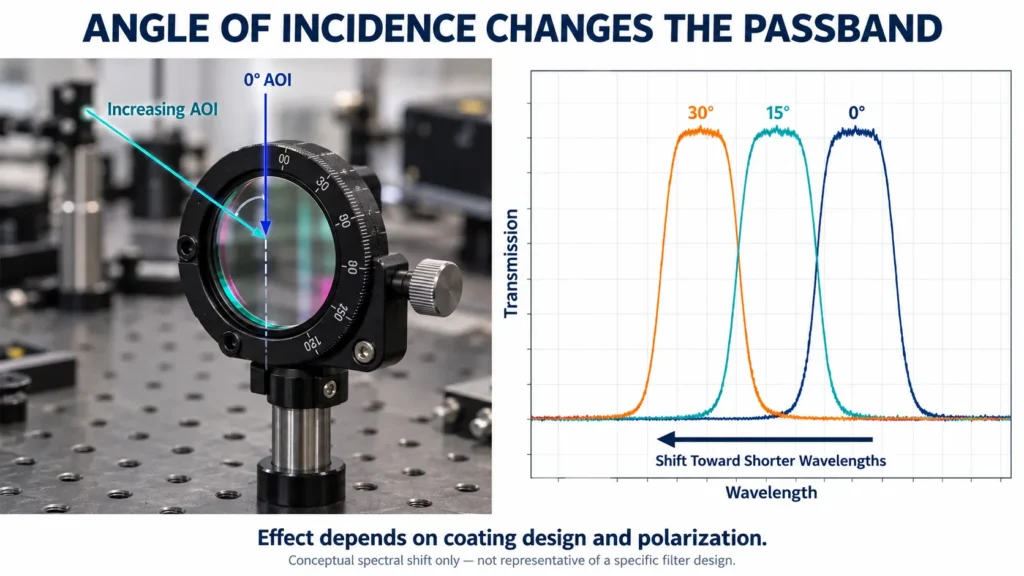
The spectral response of an interference filter changes with angle of incidence.
As the angle increases, the passband typically shifts toward shorter wavelengths. This is commonly called a blue shift.
At nonzero angles, s- and p-polarized light can also produce different spectral responses. The difference becomes more important at larger angles and with narrowband filters.
Therefore, specify:
- Nominal angle of incidence
- Allowed angular range
- Cone angle or system f-number
- Polarization state
- Required performance at the operating angle
A filter designed for normal incidence may not meet its CWL specification when installed at a substantial angle. In a converging beam, the distribution of incidence angles can shift and broaden the passband and reduce edge steepness. Provide the system f-number or cone angle so performance can be evaluated across the full illumination geometry.
 Bandpass Filter Angle of Incidence Shift
Temperature Effects
Temperature can change the optical thickness of the coating layers and shift the passband.
The amount of shift depends on:
- Coating materials
- Substrate
- Filter design
- Temperature range
- Mounting stress
- Heating rate
For stable laboratory conditions, the shift may be small. In outdoor, aerospace or industrial systems, it may need to be included in the wavelength tolerance.
The RFQ should state the operating and storage temperature ranges when spectral position is critical.
Peak Transmission and Average Transmission
Peak transmission is the highest transmission value within the passband.
Average transmission describes the mean transmission over a specified wavelength interval.
These values are not interchangeable. A filter can have high peak transmission but lower average transmission because of a narrow or rounded passband.
A measurable requirement might state:
Tavg ≥85% from 497–503 nm
or:
Tpeak ≥90%
The correct choice depends on whether the system needs maximum signal at one wavelength or consistent transmission across the band.
Edge Steepness and Passband Shape
FWHM does not describe how quickly transmission changes at the band edges.
Some applications require steep edges to separate closely spaced wavelengths. Others can accept a rounded passband.
Additional specifications may include:
- Cut-on wavelength
- Cut-off wavelength
- 10% transmission points
- 90% transmission points
- Edge slope
- Passband ripple
- Blocking transition width
Adding tight edge requirements can increase coating complexity and cost. Specify them only when they affect system performance.
How to Specify a Bandpass Filter
A practical RFQ should include:
- CWL and tolerance
- FWHM and tolerance
- Minimum peak or average transmission
- Required OD, stated as average or absolute/minimum
- Blocking wavelength range
- Spectral resolution or verification method, especially for high OD
- Allowed passband ripple when relevant
- Angle of incidence
- Polarization
- Operating temperature
- Clear aperture
- Filter dimensions
- Surface quality
- Transmitted wavefront when required
- Parallelism or wedge for imaging applications
- Coating orientation or preferred incident side when applicable
- Environmental durability
- Quantity and inspection requirements
For narrowband or angle-sensitive systems, provide the complete illumination geometry rather than only the nominal incidence angle.
Common Specification Mistakes
Specifying OD Without a Wavelength Range
OD must be connected to a defined blocking region.
Treating FWHM as the Full Passband
Useful transmission may extend beyond the half-maximum points. FWHM does not describe every part of the spectral shape.
Ignoring Angle of Incidence
Tilting an interference filter usually shifts the passband toward shorter wavelengths.
Using Peak Transmission and Average Transmission Interchangeably
They describe different characteristics and should be specified clearly.
Requesting Extremely Tight Values Without System Need
Tight CWL, FWHM and blocking tolerances can increase production complexity and cost.
Frequently Asked Questions
What Does OD 4 Mean?
OD 4 corresponds to a transmission of 0.01%, or attenuation by a factor of 10,000, within the specified blocking range.
Is CWL Always the Peak-Transmission Wavelength?
Not necessarily. CWL is commonly derived from the half-maximum wavelengths, while the peak may shift slightly in an asymmetric passband.
Does a 10 nm FWHM Pass Exactly 10 nm?
FWHM measures the distance between half-maximum points. Transmission may extend beyond those points at lower levels.
Why Does Tilting a Bandpass Filter Shift the Wavelength?
Changing the angle changes the effective optical thickness of the interference coating, typically moving the passband toward shorter wavelengths.
What Information Is Needed for a Custom Filter Quote?
Provide CWL, FWHM, transmission, OD, blocking range, AOI, polarization, dimensions, environment and quantity.
Custom Bandpass Filters from Chenyu Optics
Chenyu Optics supports drawing-based custom optical filters for imaging, laser, sensing, industrial and scientific systems.
Requirements can be reviewed according to:
- Center wavelength
- FWHM
- Peak or average transmission
- Optical density
- Blocking range
- Angle of incidence
- Polarization
- Filter dimensions
- Clear aperture
- Surface quality
- Optical coating
- Prototype and production quantities
- Inspection and packaging requirements
Final spectral specifications should be confirmed according to the application, approved drawing, coating design and available measurement method.
Need a Custom Bandpass Filter?
Send Chenyu Optics your CWL, FWHM, transmission, OD and blocking range, together with angle of incidence, polarization, filter dimensions and quantity. We can review the coating and manufacturing requirements before quotation.