
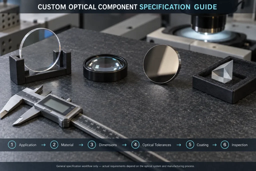
Custom optical components are normally manufactured according to a customer drawing or technical specification. A complete request for quotation helps the supplier select the correct material, manufacturing process, coating and inspection method.
Whether you need an optical window, lens, mirror, prism or filter, the specification should describe the actual system requirements without adding unnecessary tolerances that increase cost.
In This Guide
Quick Answer
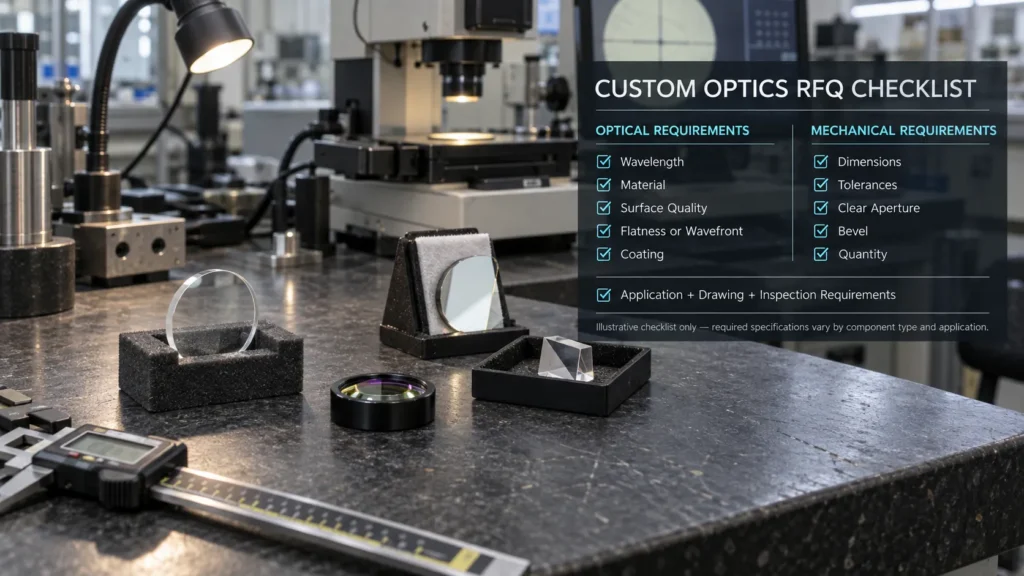
A useful custom optical component specification should include:
- Component type and optical function
- Operating wavelength or wavelength band
- Optical material and material grade
- Diameter, thickness and other dimensions
- Dimensional tolerances
- Surface quality
- Surface flatness or surface figure
- Parallelism, wedge or centration
- Clear aperture
- Optical coating requirements
- Operating environment
- Prototype and production quantities
- Inspection and documentation requirements
If a tolerance is not known, provide the system-level performance requirement instead of choosing an arbitrary value. The optical manufacturer can then recommend a practical specification.
1. Define the Application First
Begin by explaining what the component must do in the optical system.
For example, state whether the component will:
- Protect a camera or sensor
- Focus or collimate a beam
- Reflect a laser wavelength
- Separate different wavelength bands
- Change beam direction
- Transmit visible or infrared radiation
- Operate as part of an imaging system
The application helps determine which specifications are important. A protective window may emphasize durability and transmission, while an imaging lens may require tighter surface figure, centration and wavefront control.
The supplier should also know whether the component will be used in a laboratory, industrial machine, outdoor sensor, medical instrument or high-power laser system.
2. Specify the Operating Wavelength
Always provide the actual operating wavelength or wavelength band.
Examples include:
- 532 nm
- 1064 nm
- 400–700 nm
- 3–5 μm
- 8–12 μm
- 10.6 μm
The wavelength affects material selection, coating design and inspection requirements. A material that performs well in the visible spectrum may not be suitable for ultraviolet or infrared applications.
For laser systems, also specify the laser type, wavelength, pulse duration, repetition rate, beam diameter or spot size, beam profile and expected power, fluence or peak intensity as applicable. These conditions are needed to evaluate laser-induced damage risk; average power alone is not sufficient for a pulsed laser.
Avoid requesting only a “visible coating” or “infrared coating.” A measurable wavelength range and transmission or reflection target is more useful.
3. Select the Material and Grade
The drawing should identify the required material whenever possible.
Common optical materials include:
- Fused silica
- Optical glass
- Sapphire
- Silicon
- Germanium
- Calcium fluoride
- Magnesium fluoride
- Zinc selenide
- Zinc sulfide
The material grade can also be important. Different grades may have different homogeneity, inclusion levels, absorption, transmission or visible clarity.
If the material has not been selected, provide the wavelength, temperature range, mechanical environment and optical performance requirements. Chenyu Optics can review possible material options before the drawing is finalized.
Material names should not be treated as complete performance specifications. Supplier grade and inspection requirements may still need to be confirmed.
4. Define Dimensions and Mechanical Tolerances
Provide a dimensioned drawing whenever possible. State the drawing standard and revision, units, datum surfaces and any general tolerances so that the drawing is interpreted consistently by design, manufacturing and inspection teams.
For circular components, specify:
- Diameter
- Center thickness
- Diameter tolerance
- Thickness tolerance
- Edge chamfer or bevel
- Clear aperture
For rectangular or custom-shaped optics, include the length, width, thickness, corner treatment and datum surfaces.
Lens drawings may also require:
- Radius of curvature
- Effective focal length
- Back focal length
- Center thickness
- Edge thickness
- Centration
- Orientation
Effective focal length and back focal length are different measurements and should not be used interchangeably.
Tolerances should match the needs of the assembly. Excessively tight dimensional tolerances can increase manufacturing and inspection costs without improving system performance.
Custom Optical Component Specification Checklist
| Specification Area | Information to Provide | Why It Matters |
|---|---|---|
| Application | Imaging, laser, sensing, protection or beam control | Defines the important performance requirements |
| Wavelength | Single wavelength or operating band | Guides material and coating selection |
| Material | Material name and required grade | Affects transmission, durability and processing |
| Dimensions | Diameter, thickness, shape and tolerances | Determines manufacturing and mounting requirements |
| Optical quality | Surface quality, figure, wavefront and clear aperture | Controls imaging or beam performance |
| Coating | Band, AOI, polarization and R or T target | Defines finished optical performance |
| Environment | Temperature, humidity, pressure and abrasion exposure | Helps evaluate material and coating durability |
| Quantity | Prototype and expected production quantity | Affects process selection and pricing |
| Documentation | Inspection report, material certificate or coating data | Defines quality records supplied with the order |
The checklist provides general RFQ guidance. Final requirements depend on the component type, optical system and available inspection method.
5. Specify Optical Performance
Optical specifications should be selected according to the component’s function.
Surface Quality
Surface quality describes visible surface defects such as scratches and digs. Typical specifications may include 80-50, 60-40, 40-20 or 20-10.
A tighter scratch-dig value does not automatically guarantee better surface figure or lower roughness. These are separate specifications.
Clearly identify the applicable surface-imperfection standard. MIL-PRF-13830B uses visual scratch-dig comparison, while the ISO 10110-7 dimensional method controls defect area. ISO drawings may also use the visibility method—for example, 5/60-40 can correspond to a MIL-style 60-40 requirement—so the method and standard must be stated rather than inferred from the two numbers alone.
Surface Flatness or Surface Figure
Flatness is commonly specified for optical windows, mirrors and flats. Curved lenses normally require a surface figure or power and irregularity specification.
When the drawing uses values such as λ/2, λ/4 or λ/10, state the test wavelength, clear aperture and whether the requirement is peak-to-valley or RMS. Also clarify whether power is included or specified separately from irregularity.
Transmitted or Reflected Wavefront
For imaging systems, interferometers or beam-delivery systems, transmitted wavefront error may be more relevant than individual surface flatness.
Mirrors may instead require reflected wavefront performance.
The specification should identify:
- Test wavelength
- Clear aperture
- Measurement condition, including the mounted or unmounted state
- Single-pass or double-pass test configuration
- Peak-to-valley or RMS requirement
Parallelism, Wedge and Centration
Parallelism or wedge is important for windows and filters because it affects beam deviation and unwanted interference.
Lens centration controls the relationship between the mechanical and optical axes. Tight centration may be necessary for imaging lenses but unnecessary for a basic protective window.
Clear Aperture
The clear aperture defines the usable optical area. It should normally be specified as a diameter, dimension or percentage of the full component area.
6. Describe the Optical Coating
Do not specify only “AR coated” or “mirror coated.”
A useful coating specification should include:
- Operating wavelength or band
- Angle of incidence
- Polarization when relevant
- Required transmission or reflectance
- Number of coated surfaces
- Environmental durability
- Laser damage requirement when applicable
For example:
Ravg < 0.5% per surface from 450–650 nm at 0° AOI, measured under the specified polarization condition
Here, Ravg means average reflectance across the stated wavelength band. If maximum reflectance at every wavelength is required instead, specify Rmax rather than Ravg.
For angled filters or mirrors, the angle of incidence and polarization can significantly change spectral performance.
If the component has different coatings on each side, clearly identify Side 1 and Side 2 on the drawing.
7. Include Environmental Requirements
Tell the supplier about the conditions in which the optic will operate.
Relevant information may include:
- Minimum and maximum temperature
- Thermal cycling
- Humidity
- Vacuum or pressure
- Outdoor exposure
- Abrasion or cleaning
- Chemical exposure
- Shock and vibration
- Sealing or mounting method
These conditions can influence material, coating and edge-treatment recommendations.
8. State Quantity and Inspection Requirements
Provide both the initial order quantity and the expected production quantity.
A request for five prototypes may use a different manufacturing process from an annual requirement of several thousand components.
Also state whether you require:
- Standard inspection
- Dimensional inspection report
- Material certificate
- Coating measurement
- Interferometric report
- First article inspection
- Individual serial numbers
- Special packaging
Inspection requirements should be agreed upon before production because additional documentation and testing may affect cost and lead time.
Common Specification Mistakes
Adding Unnecessary Tight Tolerances
Tighter specifications usually increase processing and inspection costs. Apply them only where they improve system performance.
Mixing Different Standards
ISO 10110 dimensional defect callouts and MIL-style visual scratch-dig descriptions use different evaluation methods. Because ISO drawings can also use a visibility callout, the drawing should clearly state both the method and intended standard.
Specifying a Coating Without a Wavelength
“AR coated” is not a complete requirement. Include the wavelength band, angle of incidence and transmission or reflection target.
Confusing Surface Quality With Flatness
Surface quality controls scratches and digs. Flatness or surface figure controls the shape of the optical surface.
Omitting the Application
A drawing without application information makes it harder for the supplier to identify risks or recommend practical alternatives.
Frequently Asked Questions
Do I Need a Complete Optical Drawing?
A complete drawing is preferred, but an initial quotation may be possible using a sketch, dimensions and performance requirements. The final drawing should be confirmed before production.
What If I Do Not Know the Correct Tolerance?
Describe the system requirement and intended application. The manufacturer can recommend a practical tolerance based on available processes and inspection methods.
Should I Specify Material or Optical Performance?
Specify both when the material is fixed. If material selection is flexible, provide the wavelength, environment and required optical performance.
Can a Prototype Specification Be Used for Production?
Usually yes, but the design may need a manufacturing review before higher-volume production. Quantity can affect tooling, inspection and process selection.
Does Every Optical Component Need an AR Coating?
No. A coating should be selected according to transmission, reflection, wavelength, durability and cost requirements. Some protective windows can be used without a coating.
Custom Optical Components from Chenyu Optics
Chenyu Optics supports drawing-based custom optical components for imaging, laser, sensing, industrial and scientific systems.
Available components include:
- Optical windows
- Spherical and aspheric lenses
- Mirrors
- Prisms
- Optical filters
- Fused silica and optical glass components
- Infrared optical components
- Coated optical substrates
For quotation review, send us your drawing together with the application, wavelength, material, dimensions, coating requirements, quantity and inspection requirements.
Final specifications should be confirmed according to the customer drawing, application requirements, manufacturing capability and available inspection method.
Need Help Reviewing Your Optical Specification?
Send Chenyu Optics your drawing or preliminary requirements. We can review the material, tolerances, coating and inspection details before quotation.