
An optical window exposed to pressure or vacuum must remain mechanically safe while maintaining the required optical performance. Thickness cannot be selected from the outside diameter alone.
The correct design depends on differential pressure, unsupported aperture, material strength, window shape, edge support, surface condition, temperature and safety factor. Because optical materials are brittle and their strength varies with surface damage and load duration, general formulas should be used only for preliminary estimation.
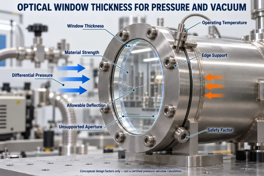 Optical Window Thickness for Pressure and Vacuum
In This Guide
Quick Answer
An initial optical-window thickness review requires:
- Maximum pressure on each side
- Maximum differential pressure
- Pressure direction
- Outside dimensions
- Unsupported aperture
- Window shape
- Material and grade
- Elastic modulus and Poisson’s ratio
- Appropriate design strength
- Edge support condition
- Operating temperature
- Required safety factor
- Allowable deflection
- Required transmitted wavefront
- Applicable pressure-vessel or safety requirements
Do not use a universal diameter-to-thickness ratio for a safety-critical window. The calculation must use the actual support condition and material data.
Optical glass strength is affected by surface condition, stressed area, load duration and environment. SCHOTT specifically identifies vacuum windows as an application where atmospheric pressure creates tensile stress in the glass. SCHOTT TIE-31
1. Calculate Differential Pressure
Window loading is based on the difference between the pressures on its two sides:
ΔP = |P₁ − P₂|
Where:
- ΔP = differential pressure
- P₁ = absolute pressure on Side 1
- P₂ = absolute pressure on Side 2
A vacuum window is not unloaded. If one side is near vacuum and the other side is exposed to normal atmospheric pressure, the window experiences approximately one atmosphere of differential pressure.
Use absolute pressure when calculating the difference. Do not confuse gauge pressure with absolute pressure.
The design should consider:
- Normal operating pressure
- Maximum expected pressure
- Start-up and shutdown
- Venting or pumping sequences
- Pressure reversal
- Accidental overpressure
- Required proof or qualification testing
2. Identify the Unsupported Aperture
The unsupported aperture is the window area spanning the opening in the mount. It is often smaller than the window’s outside diameter.
For example, a 75 mm window may rest on a sealing shoulder around a 60 mm opening. The structural span is therefore based primarily on the 60 mm unsupported aperture—not the full outside diameter.
The drawing should show:
- Window outside diameter
- Clear aperture
- Unsupported aperture
- Support diameter
- Seal position
- Edge engagement
- Contact width
A small increase in unsupported diameter can significantly increase stress and deflection. This dimension must be confirmed before thickness is finalized.
3. Preliminary Thickness Relationship
For a flat circular window under uniform pressure, classical plate theory shows that maximum stress generally follows a relationship of the form:
σmax ≈ K × ΔP × a² ÷ t²
Rearranging for thickness:
t ≈ a × √(K × ΔP ÷ σallow)
Where:
- σmax = estimated maximum stress
- K = coefficient determined by shape and edge support
- ΔP = differential pressure
- a = unsupported radius
- t = window thickness
- σallow = allowable design stress
This equation shows the main relationship: required thickness increases with unsupported aperture and pressure, and decreases when a higher allowable design stress is justified. It is a scaling relationship for preliminary screening, not a universal pressure-window calculator. The coefficient and stress location depend on geometry, Poisson’s ratio and the actual boundary condition.
However, K is not universal. A clamped window, simply supported window, bonded window and gasket-mounted window have different boundary conditions.
The allowable stress must not be taken directly from a typical strength value. Brittle-material design requires appropriate statistical treatment, surface and edge-condition assumptions, stressed area, humidity, load-duration effects and a safety factor. SCHOTT’s guidance on optical-glass bending strength discusses Weibull-based strength evaluation for applications including vacuum windows. If deflection is no longer small compared with thickness, classical small-deflection plate equations are not adequate; nonlinear plate analysis or finite-element analysis may be required.
Pressure Window Calculation Inputs
| Input | What to Specify | Why It Matters |
|---|---|---|
| Differential pressure | Normal and maximum ΔP | Determines the applied load |
| Unsupported aperture | Actual opening under the window | Strongly affects stress and deflection |
| Window shape | Circular, square or rectangular | Changes stress distribution |
| Material | Exact material and grade | Defines mechanical and thermal properties |
| Thickness | Nominal value and tolerance | Minimum finished thickness must remain safe |
| Edge support | Clamped, supported, bonded or sealed | Determines the calculation coefficient |
| Surface condition | Polished quality and allowed defects | Affects brittle-material strength |
| Temperature | Operating range and gradients | Can add thermal stress |
| Load duration | Short-term or continuous | Long-term loading can reduce design strength |
| Safety factor | Based on risk and governing rules | Provides design margin |
| Optical limit | Allowable deflection or wavefront error | May require more thickness than strength alone |
| Testing | Proof, leak or qualification testing | Confirms the completed assembly |
These inputs support preliminary evaluation only. Final pressure-window design requires qualified structural review.
4. Check Deflection
A window may survive the pressure load but bend enough to affect optical performance.
For a thin flat plate under uniform pressure, deflection generally follows:
wmax ≈ C × ΔP × a⁴ ÷ (E × t³)
Where:
- wmax = maximum central deflection
- C = coefficient determined by support condition and Poisson’s ratio
- E = elastic modulus
- Other symbols are as previously defined
Deflection is highly sensitive to aperture and thickness. Increasing thickness generally reduces bending substantially, while increasing the unsupported aperture can increase it rapidly.
Pressure-induced deformation can affect:
- Transmitted wavefront
- Focus position
- Image quality
- Beam direction
- Interference fringes
- Seal performance
For precision systems, specify the maximum allowable transmitted wavefront under operating pressure rather than only in the unmounted state.
5. Select the Correct Material Data
Material strength should not be represented by a single universal number.
Review:
- Elastic modulus
- Poisson’s ratio
- Fracture behavior
- Statistical strength data
- Surface finish
- Edge condition
- Stress-corrosion behavior
- Thermal expansion
- Operating temperature
- Load duration
Materials such as fused silica, BK7, sapphire, calcium fluoride, germanium and zinc selenide have very different properties.
NASA life-prediction research on sapphire windows notes that brittle window materials require reliability and life evaluation because strength is influenced by flaws, slow crack growth and stress-corrosion behavior.
Do not substitute one optical material for another while retaining the original thickness calculation.
6. Include a Safety Factor
A safety factor accounts for uncertainties in material strength, surface damage, load, mounting and manufacturing variation.
The required factor depends on:
- Consequence of failure
- Human exposure
- Stored pressure energy
- Material variability
- Inspection level
- Load duration
- Environment
- Governing regulations
A laboratory viewport and a personnel-accessible pressure-vessel window may require different design approaches.
Pressure equipment may also fall under regulations or codes such as ASME BPVC Section VIII, which addresses design, fabrication, inspection, testing and certification of pressure vessels within its scope. Applicability—including pressure thresholds, equipment classification and local jurisdiction—must be determined by the responsible engineer and authority having jurisdiction. The preliminary relationships in this article do not demonstrate code compliance.
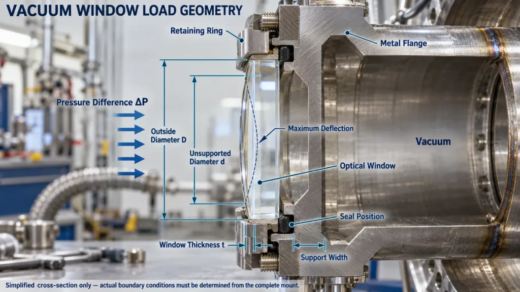 Vacuum Window Pressure Load Diagram
7. Mounting and Sealing
The mount determines how load transfers from the window into the housing.
Common arrangements include:
- Gasket-supported windows
- Retaining rings
- Elastomeric seals
- Bonded assemblies
- Brazed or soldered seals
- Metal-to-glass seals
Avoid concentrated edge loads and direct contact between brittle glass and sharp metal features. The design should provide controlled support and allow for dimensional tolerances.
Overtightening a retaining ring can introduce stress before pressure is applied. Uneven seals can also bend the window and reduce transmitted-wavefront performance.
8. Include Temperature Effects
Pressure and thermal loads may act at the same time.
Evaluate:
- Minimum and maximum temperature
- Temperature gradients
- Heating and cooling rate
- Thermal expansion of the window
- Expansion of the mount
- Seal and adhesive limits
- Coating temperature limits
Rapid temperature changes can create tensile stress within optical glass. A thicker window is not automatically safer if it develops a large thermal gradient.
9. Consider Minimum Finished Thickness
Manufacturing requires a thickness tolerance. The safety analysis should normally use the minimum permitted finished thickness rather than the nominal drawing value.
For example, if a window is specified as:
10.0 ±0.2 mm
The structural review should consider a finished thickness of 9.8 mm unless another controlled minimum is defined.
Coating, polishing and edge processing should also be included in the final drawing.
Common Calculation Mistakes
Using Outside Diameter Instead of Unsupported Aperture
Structural loading depends primarily on the unsupported span and edge condition.
Treating Tensile Strength as Allowable Stress
Published strength values are not automatically safe design values for brittle optical materials.
Ignoring Long-Term Loading
A continuously loaded vacuum window may require different strength assumptions from a short test load.
Checking Breakage but Not Deflection
Optical performance or sealing may fail before the material breaks.
Ignoring the Complete Assembly
The window, gasket, retaining ring, housing, temperature and pressure must be evaluated together.
Frequently Asked Questions
Does a Vacuum Window Experience Pressure?
Yes. A window separating vacuum from normal atmosphere experiences approximately one atmosphere of differential pressure.
Can I Use a Diameter-to-Thickness Rule?
Only for rough screening. It should not replace a calculation using the actual material, support condition and safety requirements.
Is Fused Silica Always Better Than BK7?
No. Fused silica has useful thermal properties, but final thickness depends on verified mechanical data and the complete design.
Does Increasing Thickness Reduce Deflection?
Generally yes. Plate deflection is strongly dependent on thickness, but mounting and optical requirements must also be considered.
Can Chenyu Optics Certify a Pressure-Window Design?
Chenyu Optics can review optical manufacturing feasibility. Final structural safety and regulatory approval must be completed by the customer’s qualified engineer or responsible certification authority.
Custom Pressure and Vacuum Windows from Chenyu Optics
Chenyu Optics supports drawing-based custom optical windows for vacuum, pressure, imaging, laser and industrial systems.
Requirements can be reviewed according to:
- Optical material
- Outside dimensions
- Thickness and tolerance
- Unsupported aperture
- Surface quality
- Surface flatness
- Parallelism or wedge
- Clear aperture
- Transmitted wavefront
- Optical coating
- Edge and sealing requirements
- Inspection and packaging
Final thickness and mounting design must be approved according to the customer’s structural analysis and applicable safety requirements.
Request a Custom Optical Window Quote
Send Chenyu Optics your approved drawing, material, dimensions, minimum thickness, wavelength, coating, quantity and inspection requirements. Final structural safety and regulatory approval remain the responsibility of the customer’s qualified engineer.