
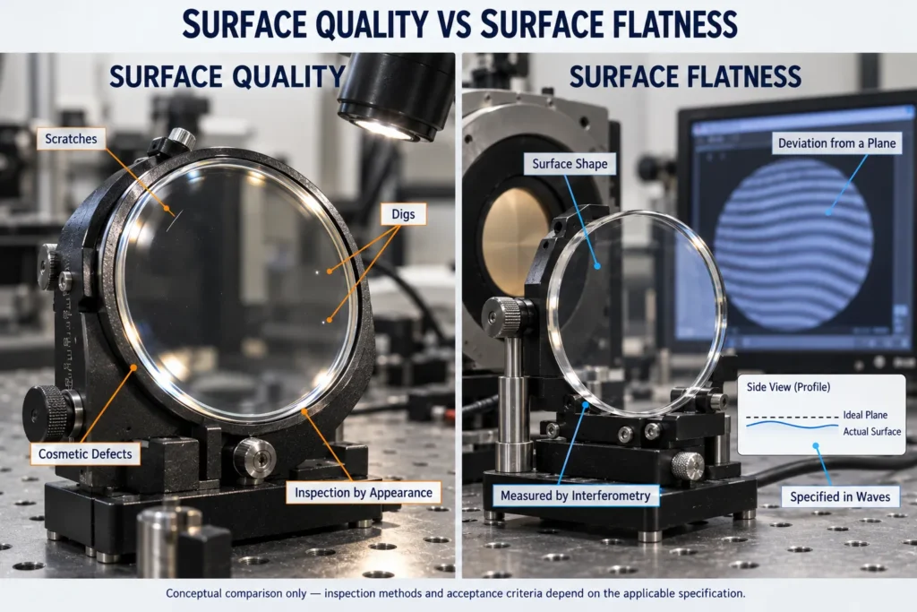
Surface quality and surface flatness describe two different characteristics of an optical surface. Surface quality controls visible defects such as scratches and digs, while surface flatness controls how closely a polished surface matches an ideal plane.
These specifications are not interchangeable. An optical window can have very few scratches but poor flatness, or excellent flatness with cosmetic surface defects. Understanding the difference helps buyers avoid unnecessary tolerances and specify optical components correctly.
In This Guide
Quick Answer
Surface quality describes localized cosmetic defects on a polished optical surface, primarily scratches and digs. It is commonly expressed using values such as 80-50, 60-40, 40-20 or 20-10 under a stated inspection standard.
Surface flatness describes the overall deviation of a polished flat surface from an ideal plane. It is commonly expressed in waves, such as λ, λ/2, λ/4 or λ/10, at a specified test wavelength and aperture.
A lower scratch-dig value generally represents tighter surface-quality requirements. A smaller wave value generally represents tighter flatness. However, improving one specification does not automatically improve the other.
What Is Optical Surface Quality?
Optical surface quality describes visible imperfections produced during material preparation, polishing, handling or coating.
The most common defects are:
- Scratches
- Digs
- Pits
- Sleeks
- Edge chips
- Coating defects
- Stains or handling marks
Scratch-dig specifications normally use two numbers. In a value such as 60-40, the first number is the scratch visibility designation and the second is the dig designation. Under traditional MIL-style inspection, scratch numbers are established primarily by visual comparison with a calibrated standard rather than by directly measuring scratch width; dig acceptance is based on defect size and the rules of the stated standard.
Common specifications include:
- 80-50: General commercial or noncritical applications
- 60-40: Many standard imaging and optical-window applications
- 40-20: More demanding imaging and laser applications
- 20-10: Precision optics requiring tighter cosmetic control
These examples are not universal recommendations. The correct requirement depends on beam size, power, image sensitivity and the position of the optic within the system.
Surface quality should always be linked to an inspection standard and its revision. MIL-style scratch-dig notation and ISO 10110-7 use different methods of classifying imperfections and should not be treated as automatically equivalent. ISO 10110-7 can specify imperfections by affected area or by visibility, so an ISO callout should be written in the required ISO drawing format rather than converted informally from a MIL value.
Why Does Surface Quality Matter?
A scratch or dig can scatter light. Depending on the application, scattered light may reduce contrast, create stray-light problems or produce visible artifacts.
Surface quality can be important in:
- High-power laser systems
- Precision imaging
- Microscopy
- Spectroscopy
- Inspection systems
- Optics near an image plane
- Systems sensitive to stray light
However, a tighter cosmetic specification does not always improve system performance. Small imperfections may have little practical effect in a general protective window or a large-beam low-power system.
Specifying 20-10 when 60-40 is adequate can increase polishing, inspection and rejection costs. Scratch-dig alone does not guarantee laser-induced damage threshold, surface roughness, cleanliness or total scatter; specify those requirements separately when they affect system performance.
What Is Optical Surface Flatness?
Surface flatness describes the difference between an actual polished surface and an ideal reference plane.
No manufactured surface is perfectly flat. Small high and low areas remain after polishing. These deviations can be measured with an interferometer by comparing the test surface with a calibrated reference surface.
Flatness is commonly expressed relative to the test wavelength:
- λ
- λ/2
- λ/4
- λ/10
At a 632.8 nm test wavelength, λ/4 represents a smaller permitted deviation than λ/2. The wavelength must be stated because “λ/4” alone does not provide a complete physical value. Under current ISO 10110-5 practice, nanometres are preferred for surface-form tolerances; wave or fringe-spacing notation may still be used when the reference wavelength is explicitly identified.
The specified aperture is also important. A flatness requirement over the central 80% may produce a different result from the same requirement applied over nearly the full diameter.
Why Does Surface Flatness Matter?
Surface flatness can influence reflected wavefront and, together with the second surface and material properties, transmitted wavefront.
Flatness may be important for:
- Optical flats
- Laser windows
- Interferometer components
- Precision mirrors
- Beam splitters
- Imaging-system windows
- Reference surfaces
For a simple protective cover, a moderate flatness specification may be sufficient. For an interferometric reference or precision laser application, a substantially tighter value may be required.
A flatness specification should state whether it applies to each individual surface or to the complete component’s optical performance.
Surface Quality vs Surface Flatness
| Comparison | Surface Quality | Surface Flatness |
|---|---|---|
| What it describes | Localized cosmetic imperfections | Overall deviation from an ideal plane |
| Typical defects or errors | Scratches, digs, pits and sleeks | Surface peaks, valleys and shape error |
| Common notation | 80-50, 60-40, 40-20 or 20-10 | λ, λ/2, λ/4 or λ/10 |
| Typical inspection | Visual comparison or standard-defined inspection | Interferometric measurement |
| Main optical effect | Light scatter and cosmetic appearance | Reflected or transmitted wavefront change |
| Required reference | Inspection standard | Test wavelength and aperture |
| Does a smaller value mean tighter control? | Generally yes | Yes |
| Are the two specifications interchangeable? | No | No |
The values shown are common examples. Acceptance criteria depend on the applicable standard, component type and measurement method.
How Is Surface Quality Inspected?
Surface quality is commonly evaluated under controlled lighting using a specified visual-comparison or inspection procedure.
The inspection may consider:
- Defect visibility
- Scratch appearance
- Dig diameter
- Number of defects
- Defect location
- Clear aperture
- Inspection illumination
Scratch designations in traditional scratch-dig systems are often based on visual comparison rather than a direct measurement of scratch width. This is one reason the governing standard should be stated on the drawing.
Inspection conditions can affect whether a defect is visible. Magnification, lighting angle and illumination intensity should follow the agreed method rather than being selected arbitrarily during final inspection.
How Is Surface Flatness Measured?
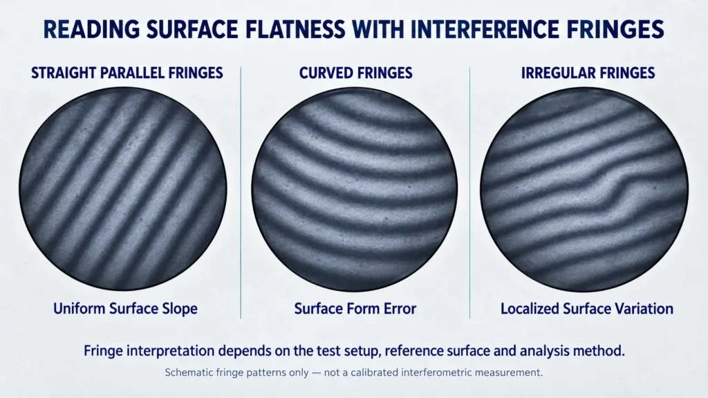
Surface flatness is commonly measured using an optical interferometer and a reference flat.
When the test and reference surfaces are compared, interference fringes show differences in optical path. The measured pattern is analyzed to determine the surface shape.
A complete flatness requirement should identify:
- Test wavelength
- Measurement aperture
- Peak-to-valley or RMS value
- Surface orientation when relevant
- Whether power is included or removed
- Required inspection report
Flatness results can change depending on how the optic is supported. A thin window may deform under its own weight or from the inspection fixture. The agreed support condition becomes important for flexible components.
Surface Flatness vs Transmitted Wavefront
Surface flatness and transmitted wavefront are also different specifications.
Surface flatness measures one polished surface. Transmitted wavefront evaluates how the complete component changes a wavefront passing through it. For a reflecting surface near normal incidence, surface-form error contributes approximately twice that amount to reflected wavefront error; this should not be confused with transmission through a window.
The transmitted result can be affected by:
- Flatness of the first surface
- Flatness of the second surface
- Surface parallelism or wedge
- Material homogeneity
- Internal stress
- Window thickness
- Mounting stress
- Test wavelength
For an optical window used in a precision imaging or laser system, transmitted wavefront may describe finished performance better than individual-surface flatness alone.
How Tight Should Surface Quality Be?
Choose surface quality according to the sensitivity of the application.
A general protective window may use a commercial specification such as 60-40. Lower-scatter imaging, spectroscopy or laser applications may need 40-20 or tighter, but the value should be selected from a performance-based stray-light, contamination and damage-risk assessment rather than from laser power alone.
Consider:
- Laser power density
- Beam diameter
- Defect location
- Distance from an image plane
- Stray-light sensitivity
- Required image contrast
Avoid selecting the tightest available value simply because it appears to indicate higher quality.
How Tight Should Surface Flatness Be?
Flatness should be based on permitted wavefront error and the function of the component.
A protective window may accept λ/2 or another commercial tolerance, while a precision flat or interferometric component may need λ/10 or better under defined measurement conditions.
The correct value also depends on:
- Component diameter
- Component thickness
- Material
- Clear aperture
- Mounting method
- Operating temperature
- Manufacturing feasibility
Large, thin windows are more difficult to maintain at tight flatness because they can flex during polishing, measurement and installation.
Common Specification Mistakes
Treating Surface Quality as Flatness
A 20-10 surface-quality requirement does not indicate that the surface is flat. Separate flatness specifications are still required.
Writing Only “λ/4”
Always include the test wavelength and measurement aperture. State whether the value is peak-to-valley or RMS when applicable.
Mixing Inspection Standards
Do not assume that a MIL-style scratch-dig value directly equals an ISO 10110 imperfection requirement.
Applying Tight Specifications Everywhere
The full outside diameter may not need optical control. Defining an appropriate clear aperture can improve manufacturability.
Ignoring the Installed Condition
A component may meet flatness in a free state but deform after clamping, sealing or temperature change.
How to Specify Both Requirements
A practical drawing entry might contain:
- Surface quality: 60-40 scratch-dig according to the stated standard
- Surface flatness: λ/4 PV at 632.8 nm
- Clear aperture: Central 90% of the diameter
- Inspection condition: Unmounted or supported as agreed
- Transmitted wavefront: Added separately when required
The exact format should follow the drawing standard and inspection method accepted by both customer and manufacturer.
Frequently Asked Questions
Does Better Surface Quality Mean Better Flatness?
No. Surface defects and surface-form error result from different characteristics and require separate inspection.
Is 20-10 Better Than 60-40?
It is a tighter cosmetic requirement, but it is not automatically better for every application. The appropriate value depends on optical performance and cost.
Is λ/10 Flatter Than λ/4?
Yes, when both values use the same wavelength, aperture and measurement definition.
Can Surface Flatness Be Checked Visually?
Interference fringes may be visually observed, but reliable quantitative flatness normally requires a controlled interferometric setup and defined analysis method.
Does an Optical Window Need Both Specifications?
It depends on the function. Surface quality is commonly specified for polished windows, while surface flatness or transmitted wavefront should be added when surface form or installed optical performance matters. A noncritical protective cover may not need a tight flatness requirement.
Custom Optical Components from Chenyu Optics
Chenyu Optics supports drawing-based production of custom optical windows, lenses, mirrors, prisms and coated substrates.
Requirements can be reviewed according to:
- Optical material
- Component dimensions
- Surface quality
- Surface flatness
- Transmitted wavefront
- Parallelism or wedge
- Clear aperture
- Surface coating
- Prototype and production quantities
- Inspection and packaging requirements
Final specifications should be confirmed according to the application, approved drawing, applicable standard and available inspection method.
Need Help Selecting Surface Specifications?
Send Chenyu Optics your component drawing, material, dimensions, wavelength, surface-quality requirement, flatness requirement, coating and quantity. If the correct tolerances are not known, provide the application and required optical performance for review.