
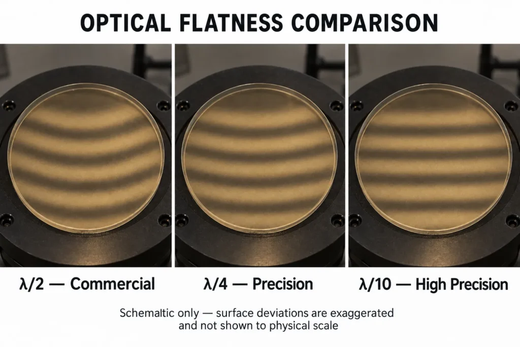
Optical flatness describes how closely a polished surface matches an ideal plane. It is commonly specified as a fraction of a reference wavelength, such as λ/2, λ/4 or λ/10.
A smaller fraction represents a tighter flatness requirement. At a 632.8 nm test wavelength, λ/2 corresponds to approximately 316 nm of peak-to-valley surface deviation, while λ/10 corresponds to approximately 63 nm, provided the same measurement definition and evaluated aperture are used.
The appropriate flatness depends on the component’s function. General-purpose optics may use λ/2 or a looser requirement, precision imaging and beam-delivery components often use λ/4, and demanding interferometric, mirror or wavefront-sensitive systems may require λ/10 or better.
In This Guide
Quick Answer: Which Optical Flatness Should You Choose?
Choose λ/2 for general-purpose windows, protective covers and applications where moderate surface-form error is acceptable. Some noncritical commercial windows can use a looser specification such as 1λ.
Choose λ/4 for precision imaging, beam delivery and many low-to-moderate-power laser applications.
Choose λ/10 for interferometry, precision mirrors, high-quality laser systems and applications sensitive to wavefront distortion.
Specify the test wavelength because λ is a physical wavelength rather than a fixed distance.
Specify the clear aperture because flatness measured over a small central area may differ from flatness over the full polished surface.
Important: Surface flatness does not automatically define transmitted wavefront, parallelism, surface roughness or scratch-dig quality. These requirements should be specified separately when relevant.
What Does Optical Flatness Mean?
Surface flatness is the peak-to-valley deviation of a nominally flat optical surface from an ideal plane.
Peak-to-valley, or PV, measures the height difference between the highest and lowest evaluated points. The drawing or inspection agreement should define the clear aperture and which fitted terms—such as tilt and, when applicable, power—are removed before the result is reported.
Flatness is commonly expressed in waves:
Physical flatness error = test wavelength ÷ specified denominator
At a reference wavelength of 632.8 nm:
- λ/2 ≈ 316.4 nm PV
- λ/4 ≈ 158.2 nm PV
- λ/10 ≈ 63.3 nm PV
These numbers change if a different reference wavelength is used. A drawing that states only “λ/4 flatness” without identifying the wavelength may therefore be ambiguous.
λ/2 vs λ/4 vs λ/10 Flatness
| Flatness | Approximate PV at 632.8 nm | General level | Typical applications |
|---|---|---|---|
| λ/2 | 316 nm | General purpose | Protective windows and general instruments |
| λ/4 | 158 nm | Precision | Imaging, beam delivery and many laser systems |
| λ/10 | 63 nm | High precision | Interferometry, precision mirrors and demanding laser optics |
Note: These values assume a 632.8 nm reference wavelength and a PV surface-deviation specification. Final suitability also depends on clear aperture, removed terms, spatial error distribution, measurement method, mounting and complete system requirements.
What Is λ/2 Flatness?
λ/2 is a practical specification for general-purpose optical components where moderate surface-form error is acceptable. Noncritical commercial windows may use a looser requirement, while the correct choice should come from the allowable system wavefront error.
Typical applications include:
- Protective sensor windows
- General illumination systems
- Industrial instruments
- Noncritical viewing windows
- Basic laboratory assemblies
A λ/2 surface can still be precisely polished, but it allows more departure from an ideal plane than λ/4 or λ/10.
It may be sufficient when the optic is used with a large beam, is positioned far from a focus or does not control a critical reflected wavefront.
What Is λ/4 Flatness?
λ/4 is a common precision specification that balances optical performance and manufacturing cost.
It is often used for:
- Precision optical windows
- Imaging instruments
- Beam-delivery components
- Low-to-moderate-power laser systems
- Laboratory optics
- General precision mirrors
The actual effect on the system depends on whether the surface transmits or reflects light and how much of the clear aperture is illuminated.
λ/4 is not automatically necessary for every laser optic, but it is a useful starting point for many precision applications.
What Is λ/10 Flatness?
λ/10 is a high-precision flatness specification.
It may be required for:
- Interferometric measurements
- Precision reference surfaces
- High-quality mirrors
- Wavefront-sensitive laser systems
- High-resolution optical testing
- Demanding scientific instruments
Achieving λ/10 normally requires tighter process control, more polishing time and more accurate interferometric inspection.
For large, thin or difficult materials, λ/10 can significantly increase manufacturing cost and lead time. Mounting stress may also distort the finished component beyond its unmounted test result.
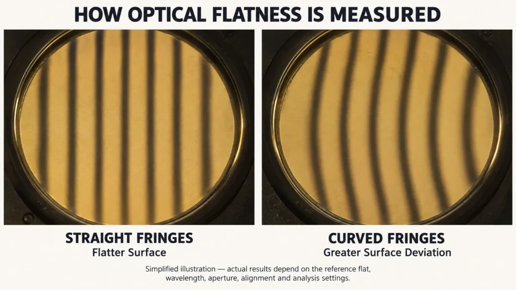
How Is Optical Flatness Measured?
Surface flatness is commonly measured with an interferometer or by comparison with a calibrated optical flat.
When the test surface and reference wavefront are compared under monochromatic light, they produce interference fringes. Straight, evenly spaced fringes indicate a flat surface relative to the reference. Curved fringes indicate surface-form error.
A modern phase-shifting interferometer can generate:
- A surface map
- Peak-to-valley error
- RMS error
- Interference fringes
- Selected spatial-frequency results
- Inspection reports
Measurement results depend on:
- Reference-flat accuracy
- Test wavelength
- Clear aperture
- Support method
- Temperature stability
- Vibration and airflow
- Removed terms and software settings
The drawing and inspection report should use the same measurement definition.
Surface Flatness vs Transmitted Wavefront
Surface flatness and transmitted wavefront error are related but not interchangeable.
Surface flatness evaluates one physical surface. Transmitted wavefront error measures how a complete optic changes a wavefront passing through it.
The transmitted wavefront of a window can be affected by:
- Flatness of both surfaces
- Surface parallelism or wedge
- Material refractive index
- Refractive-index homogeneity
- Thickness variation
- Internal stress
- Mounting distortion
A window with two λ/4 surfaces does not automatically have λ/4 transmitted wavefront performance.
For a reflective surface, the reflected wavefront error is approximately twice the surface-height error at normal incidence. Therefore, mirror specifications must clearly distinguish between surface flatness and reflected wavefront error.
Flatness vs Surface Quality and Roughness
Flatness describes large-scale deviation from an ideal plane.
It does not describe:
- Scratches and digs
- Microscopic surface roughness
- Parallelism
- Wedge
- Cosmetic coating defects
- Laser-induced damage threshold
For example, a component may meet λ/10 flatness but have unacceptable scratches. Another component may have 20-10 surface quality but fail its flatness requirement.
Each parameter controls a different part of optical performance and should be specified separately.
How to Choose the Right Flatness
Use the following approach:
- Identify whether the component is used in transmission or reflection.
- Determine the beam diameter and required clear aperture.
- Establish the allowable wavefront error.
- Consider the wavelength and angle of incidence.
- Review the component’s thickness and mounting method.
- Choose the least restrictive flatness that meets system performance.
A practical starting point is:
- λ/2 for general-purpose applications; noncritical commercial optics may accept 1λ or looser
- λ/4 for precision imaging and general laser systems
- λ/10 for demanding wavefront-sensitive systems
These are general guidelines, not universal design rules.
Common Specification Mistakes
Omitting the Reference Wavelength
λ/4 has a different physical value at 632.8 nm than at another test wavelength.
Omitting the Clear Aperture
The evaluated area must be defined. Flatness over the central 80% is not the same as flatness over the entire surface.
Confusing Surface Flatness with Wavefront Error
A surface result cannot automatically be used as the transmitted or reflected system wavefront.
Ignoring the Mount
A thin window may meet specification when unmounted but deform after clamping or sealing.
Automatically Specifying λ/10
A tighter requirement may increase cost without improving the actual system performance.
Frequently Asked Questions
Is λ/10 Flatter Than λ/4?
Yes. At the same reference wavelength and measurement conditions, λ/10 allows less peak-to-valley deviation than λ/4.
What Does λ Mean in a Flatness Specification?
λ represents the reference wavelength used for measurement. A common value is 632.8 nm, but the drawing should state it explicitly.
Does λ/4 Flatness Mean λ/4 Transmitted Wavefront?
No. Transmitted wavefront also depends on the second surface, wedge, thickness, refractive-index homogeneity and mounting.
Is λ/10 Necessary for Every Laser Window?
No. The correct requirement depends on beam diameter, power, position in the system and allowable wavefront distortion.
Are Flatness and Scratch-Dig the Same?
No. Flatness describes surface form, while scratch-dig describes visible localized defects.
Custom Precision Flat Optics from Chenyu Optics
Chenyu Optics manufactures custom optical windows, mirrors, filters, prisms and other precision flat optics.
Components can be evaluated according to:
- Optical material and grade
- Operating wavelength
- Dimensions and thickness
- Surface flatness
- Transmitted or reflected wavefront
- Surface quality
- Surface roughness
- Parallelism or wedge
- Clear aperture
- Optical coating
- Inspection and documentation requirements
- Prototype or production quantity
Final specifications should be confirmed according to the customer drawing, reference wavelength, clear aperture, mounting conditions and available inspection method.
Need Help Specifying Optical Flatness?
Send us your component dimensions, material, wavelength, clear aperture, coating and wavefront requirements.
Chenyu Optics can help determine whether λ/2, λ/4, λ/10 or another flatness specification is appropriate for your optical component.