
Optical component tolerances define the acceptable variation in dimensions, surface condition and optical performance. Clear tolerances help manufacturers evaluate feasibility, select an inspection method and provide an accurate quotation.
Tolerances that are too loose may cause assembly or performance problems. Tolerances that are unnecessarily tight can increase polishing, inspection, rejection and documentation costs. A good RFQ identifies the requirements that directly affect the optical system.
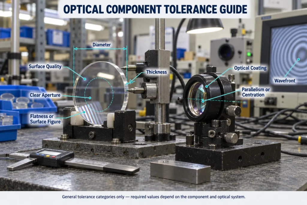 Optical Component Tolerance Guide
In This Guide
Quick Answer
A custom optical component RFQ may need the following tolerances:
- Diameter, length and width
- Center or edge thickness
- Radius of curvature
- Chamfer or bevel
- Surface quality
- Surface flatness or figure
- Parallelism or wedge
- Centration
- Clear aperture
- Effective focal length
- Transmitted or reflected wavefront
- Surface roughness
- Coating transmission or reflectance
- Spectral position and bandwidth
Not every component requires every specification. Include tolerances that control fit, optical performance, safety or environmental reliability.
If the correct manufacturing value is unknown, provide the system requirement instead. The manufacturer can then recommend a practical tolerance.
1. Dimensional Tolerances
Dimensional tolerances control whether the component fits correctly in its mount.
For circular windows, filters and mirrors, the drawing may specify:
- Outside diameter
- Diameter tolerance
- Thickness
- Thickness tolerance
- Chamfer or bevel
- Edge finish
Rectangular components may require length, width, thickness, corner radius and datum surfaces.
Lens drawings may also include:
- Center thickness
- Edge thickness
- Radius of curvature
- Effective focal length
- Back focal length
Mechanical tolerances should be based on the mount and available assembly clearance. A diameter tolerance tighter than the housing requires may add cost without improving optical performance.
For pressure or vacuum windows, thickness and outside dimensions are also part of the structural design. The final drawing should use the minimum permitted thickness established by the responsible engineer.
2. Surface Quality
Surface quality describes localized defects such as scratches and digs.
Common scratch-dig requirements include:
- 80-50
- 60-40
- 40-20
- 20-10
In a MIL-style scratch-dig designation, lower numbers generally indicate tighter acceptance criteria, but the numbers are inspection designations rather than direct physical scratch-width measurements. The appropriate requirement depends on the application and the specified inspection standard.
A general protective window may accept 60-40, while a laser or low-scatter imaging system may need 40-20 or tighter.
Surface quality does not define:
- Surface flatness
- Surface roughness
- Transmitted wavefront
- Laser-induced damage threshold
- Coating durability
The RFQ should identify the applicable inspection standard and inspection method. MIL-style scratch-dig and ISO 10110-7 surface-imperfection specifications use different evaluation systems and should not be treated as directly interchangeable.
3. Surface Flatness and Surface Figure
Flatness describes how closely a polished flat surface matches an ideal plane. It is commonly specified for windows, mirrors and optical flats.
Examples include:
- λ
- λ/2
- λ/4
- λ/10
A complete requirement should also state:
- Test wavelength
- Clear aperture
- Peak-to-valley (PV) or RMS value
- Whether the requirement applies to a single surface or to transmitted wavefront
- Support or mounting condition when important
Writing only λ/4 is incomplete if the wavelength and measurement aperture are not defined.
Curved lenses normally require a surface-figure specification rather than flatness. Surface power and irregularity may be specified separately, depending on the drawing standard and measurement method.
4. Parallelism and Wedge
Parallelism controls the angular relationship between two nominally parallel surfaces.
If an optical window has wedge, it can act like a weak prism and change the direction of the transmitted beam.
Parallelism may be specified in:
- Degrees
- Arcminutes
- Arcseconds
- Milliradians
Mechanical wedge and transmitted beam deviation are related but are not identical. Their relationship depends on refractive index, angle of incidence and the surrounding medium. The required value should therefore be derived from the permitted beam deviation and stated with the test conditions. Extremely tight parallelism may require additional polishing and measurement.
Some applications intentionally use a wedged window to separate ghost reflections. In that case, specify:
- Nominal wedge
- Wedge tolerance
- Thick-edge direction
- Allowed beam deviation
- Inspection method
5. Lens Centration
Centration describes the alignment between a lens’s optical and mechanical axes.
Poor centration can introduce:
- Image displacement
- Coma
- Asymmetric aberration
- Reduced resolution
- Assembly alignment problems
Centration may control decenter, tilt or both. It can be expressed using edge-thickness variation, runout, decenter or angular deviation, depending on the drawing standard and test method. These quantities are not universally interchangeable.
The RFQ should clearly identify the datum axis, the controlled optical surface or axis, the tolerance definition and the measurement method. For ISO drawings, use the applicable ISO 10110-6 centration and tilt notation. Two suppliers may interpret “centration” differently if these details are not stated.
Centration is generally more important for imaging lenses and multi-element assemblies than for simple illumination components.
Optical Component Tolerance Checklist
| Specification | Commonly Used For | Information to Include |
|---|---|---|
| Diameter and thickness | Windows, lenses, filters and mirrors | Nominal dimensions, units, tolerance and datums |
| Surface quality | Most polished optics | Value, standard and clear aperture |
| Flatness | Windows, mirrors and flats | Wave value, wavelength and aperture |
| Surface figure | Curved lenses and mirrors | Power, irregularity and test method |
| Parallelism or wedge | Windows, filters and plates | Angular tolerance and orientation |
| Centration | Lenses and assemblies | Datum and measurement definition |
| Wavefront | Precision imaging and laser systems | Transmitted or reflected, wavelength, PV or RMS |
| Surface roughness | Low-scatter and laser applications | Maximum value and measurement method |
| Focal length | Positive and negative lenses | EFL or BFL, reference planes or conjugates, wavelength, temperature when relevant, and tolerance |
| Coating | Coated optical components | Band, AOI, polarization, per-surface or component-level performance, and durability |
This checklist provides general RFQ guidance. The RFQ should also identify drawing revision, units, datum scheme, inspection standard, sampling or reporting requirements, operating environment, quantity and lot size. Only include tolerances required by the component’s function and assembly.
6. Clear Aperture
The clear aperture defines the usable optical area over which optical specifications apply.
It can be expressed as:
- A specific diameter
- A rectangular area
- A percentage of the component size
For example:
Clear Aperture: Central 90% of the diameter
The edge zone and bevel are normally excluded. Applying surface quality or flatness over the full physical diameter can create an impractical requirement.
If the beam does not use the entire window, define the required optical area rather than overcontrolling unused regions.
7. Transmitted and Reflected Wavefront
Transmitted wavefront describes how a complete component changes light passing through it. It can include the combined effects of:
- Both optical surfaces
- Material homogeneity
- Internal stress
- Thickness variation
- Mounting deformation
Reflected wavefront is normally used for mirrors and reflective surfaces.
A wavefront specification should identify:
- Test wavelength
- Clear aperture
- Peak-to-valley or RMS
- Test condition
- Whether certain terms are removed during analysis
For precision windows, transmitted wavefront may be more useful than specifying very tight flatness on both surfaces independently.
8. Surface Roughness
Surface roughness describes microscopic surface texture rather than visible scratches or overall surface shape.
It can affect scatter, coating performance and selected laser applications.
A roughness specification should state:
- Maximum RMS roughness
- Measurement area
- Spatial-frequency range when relevant
- Measurement method
Do not assume that a 20-10 surface-quality requirement guarantees low roughness. These specifications must be controlled separately.
9. Focal-Length Tolerance
Lens RFQs should distinguish between:
- Effective focal length
- Back focal length
- Front focal length
- Flange focal distance
- Working distance
These values are not interchangeable.
The drawing should state the focal-length definition, reference planes or conjugates, operating wavelength, tolerance and temperature when relevant. Refractive-index variation and radius tolerances can affect the finished focal length.
For broadband systems, focal length may also vary with wavelength because of material dispersion.
10. Coating Tolerances
“AR coated” is not a measurable coating specification.
Include:
- Operating wavelength or band
- Angle of incidence
- Polarization when relevant
- Maximum reflectance
- Minimum transmission
- Number of coated surfaces
- Whether performance applies per surface, as an average, as a minimum or to the complete component
- Environmental durability
- Laser requirements when applicable
Filters may additionally require:
- Center wavelength
- FWHM
- Cut-on or cut-off wavelength
- Optical density
- Blocking range
Coating tolerances should reflect actual system needs. Narrow spectral tolerances or broad high-OD blocking can significantly affect manufacturing complexity.
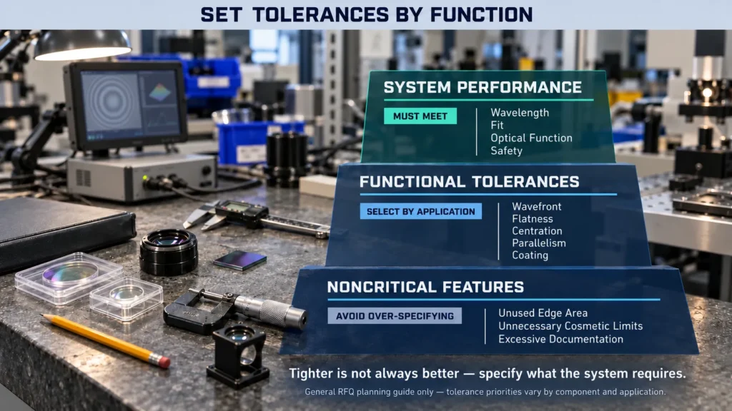 Optical Tolerance Priority Guide
How Tight Should Tolerances Be?
Use the least restrictive tolerances that still satisfy the system.
Before tightening a value, ask:
- Does this tolerance affect image quality?
- Does it control beam position?
- Is it required for assembly?
- Is it related to safety?
- Can it be measured consistently?
- Will it change the manufacturing process?
- Is an inspection report required?
Tolerances should work together. For example, extremely tight flatness may provide little benefit if mounting stress deforms the finished window.
Discuss critical values with the manufacturer before freezing the drawing.
Common RFQ Mistakes
Using Default Tight Tolerances Everywhere
Default precision values can increase cost even when the application does not need them.
Confusing Surface Quality With Flatness
Surface quality controls scratches and digs. Flatness controls overall surface shape.
Omitting the Inspection Standard
A tolerance is incomplete if the customer and manufacturer use different acceptance methods.
Forgetting the Clear Aperture
Define where optical requirements apply instead of controlling unused edge regions.
Requiring Reports That Are Not Needed
Special inspection reports add measurement time and cost. Request them only when required.
Frequently Asked Questions
Does a Smaller Tolerance Always Mean Better Quality?
It means tighter control, but it may not improve the actual system performance.
Which Tolerances Affect Price Most?
The answer depends on the component, but tight figure, wavefront, centration, surface quality and coating requirements can significantly affect cost.
Should Every Drawing Include Transmitted Wavefront?
No. It is most relevant when the complete component must preserve imaging or beam quality.
Can the Manufacturer Recommend Tolerances?
Yes. Provide the application and required system performance so manufacturable values can be reviewed.
What Should Be Included in the RFQ?
Include the drawing and revision, units, material and grade, wavelength, dimensions, datum scheme, critical tolerances, coating, operating environment, quantity or lot size, delivery requirements, inspection standard, sampling plan and required reports.
Custom Optical Components from Chenyu Optics
Chenyu Optics supports drawing-based custom windows, lenses, mirrors, prisms and filters.
Requirements can be reviewed according to:
- Material and dimensions
- Surface quality
- Flatness or surface figure
- Parallelism or centration
- Clear aperture
- Wavefront
- Optical coating
- Quantity
- Inspection and packaging
Final tolerances should be confirmed according to the application, approved drawing and available inspection method.
Request a Custom Optical Component Quote
Send Chenyu Optics your drawing, wavelength, material, critical tolerances, coating requirements and quantity. If some values have not been finalized, provide the required system performance for review.