
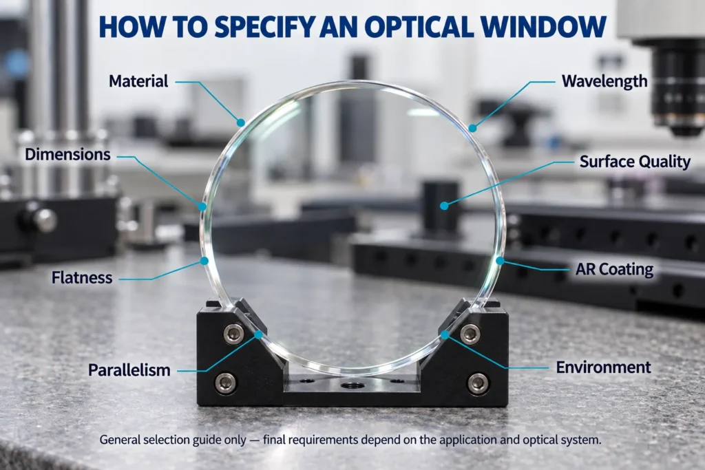
An optical window is a transparent component used to protect sensors, cameras, lasers and other optical systems without intentionally changing the optical power. Although its shape appears simple, the correct specification requires more than diameter and thickness.
Material, wavelength, surface quality, flatness, parallelism and coating performance can all affect the finished window. A clear drawing and realistic tolerances help the manufacturer provide an accurate quotation and produce a component suitable for the application.
In This Guide
Quick Answer
To specify an optical window, provide the following information:
- Intended application
- Operating wavelength or wavelength range
- Optical material and material grade
- Diameter or outside dimensions
- Thickness
- Dimensional tolerances
- Surface quality
- Surface flatness
- Parallelism or wedge
- Clear aperture
- Transmitted wavefront when required
- Optical coating performance
- Angle of incidence
- Operating environment
- Quantity and inspection requirements
The specification should describe the performance the system actually needs. Unnecessarily tight tolerances may increase production and inspection costs without improving the application.
1. Define the Window’s Function
Begin by explaining what the optical window protects and where it will be installed.
Typical applications include:
- Camera and imaging-system protection
- Laser enclosure windows
- Detector and sensor covers
- Thermal-imaging windows
- Vacuum chamber viewports
- Outdoor optical instruments
- Industrial inspection equipment
A simple protective cover may only require adequate transmission and mechanical durability. A window placed in a high-resolution imaging path may also require controlled transmitted wavefront, parallelism and coating uniformity.
The manufacturer should know whether the window is located near a focal plane, in a collimated beam or at an angle to the optical axis. These conditions can affect which specifications are most important.
2. Specify the Operating Wavelength
Always provide a measurable operating wavelength or wavelength range.
Examples include:
- 355 nm
- 532 nm
- 1064 nm
- 400–700 nm
- 3–5 μm
- 8–12 μm
- 10.6 μm
Avoid requesting only a “visible window” or “infrared window.” These descriptions are too broad for accurate material and coating selection.
For laser applications, state whether operation is continuous-wave or pulsed. For CW systems, provide optical power, beam diameter and irradiance at the window. For pulsed systems, provide pulse energy, pulse duration, repetition rate, beam diameter, fluence and peak intensity. Define the beam diameter convention—such as 1/e² diameter for a Gaussian beam—because irradiance and fluence depend on the stated spot size. These parameters help evaluate material absorption, coating absorption, contamination sensitivity and laser-induced damage risk.
3. Choose the Optical Material
The material must transmit the required wavelength and withstand the intended environment.
Common optical-window materials include:
Fused Silica
Fused silica provides good ultraviolet-to-near-infrared transmission, low thermal expansion and good thermal stability. It is widely used for imaging, laser and scientific applications.
Optical Glass
Optical glasses such as N-BK7 are economical options for many visible and near-infrared systems. They are not normally preferred for deep-ultraviolet or demanding thermal environments.
Sapphire
Sapphire offers high hardness, good abrasion resistance and a broad transmission range. Its crystalline structure and birefringence should be considered in polarization-sensitive or high-resolution systems.
Calcium Fluoride
Calcium fluoride transmits ultraviolet, visible and infrared wavelengths. It is useful for broadband and spectroscopy applications but requires appropriate mechanical handling.
Silicon and Germanium
Silicon and germanium are commonly used for infrared windows. They are opaque in the visible spectrum, and their transmission varies with wavelength, temperature, thickness and coating.
Other materials such as magnesium fluoride, zinc selenide and zinc sulfide may be selected for specialized ultraviolet or infrared applications.
Material grade should also be identified when homogeneity, inclusions, absorption or visible clarity is important.
Optical Window Specification Checklist
| Specification | Information to Provide | Why It Matters |
|---|---|---|
| Application | Imaging, laser, sensing or protection | Identifies the important performance requirements |
| Wavelength | Operating wavelength or spectral band | Determines material and coating suitability |
| Material | Material name and grade | Affects transmission, durability and temperature behavior |
| Dimensions | Diameter, length, width and thickness | Defines the physical window |
| Surface quality | Scratch-dig or applicable ISO requirement | Controls allowable cosmetic surface defects |
| Flatness | Required value, test wavelength and aperture | Controls surface shape |
| Parallelism | Angular or wedge tolerance | Controls beam deviation |
| Clear aperture | Usable optical area | Defines where optical specifications apply |
| Coating | Band, AOI and reflection or transmission target | Determines finished-window performance |
| Environment | Temperature, humidity, abrasion and pressure | Helps evaluate durability |
| Inspection | Reports, certificates and test data | Defines required quality documentation |
This table provides general specification guidance. Not every optical window requires every tolerance listed.
4. Define Dimensions and Mechanical Tolerances
For a round window, specify:
- Diameter
- Diameter tolerance
- Thickness
- Thickness tolerance
- Chamfer or bevel
- Edge finish
For a rectangular window, provide the length, width, thickness and corner requirements. Custom shapes should include a controlled drawing with datum surfaces and dimensional tolerances.
Thickness affects mechanical strength, weight, transmission and transmitted wavefront. A thicker window may withstand higher pressure but can increase absorption in some materials.
Do not apply unnecessarily tight diameter or thickness tolerances. The mounting design and available assembly clearance should determine the required values.
5. Select the Surface Quality
Surface quality describes defects such as scratches and digs. Common specifications include:
- 80-50 for general commercial applications
- 60-40 for many standard optical systems
- 40-20 for more demanding imaging or laser applications
- 20-10 for applications requiring tighter cosmetic control
These values are examples rather than universal recommendations.
Surface quality does not describe flatness, roughness or transmitted wavefront. A window can have good scratch-dig quality but unsuitable surface figure, or excellent flatness with visible cosmetic defects.
The drawing should identify the surface-imperfection method and applicable standard. MIL-PRF-13830B uses visual scratch-dig comparison, while the ISO 10110-7 dimensional method controls defect area. ISO drawings may also use a visibility method—for example, 5/60-40 has the same meaning as a MIL-style 60-40 callout—so the method and standard should be stated explicitly.
6. Specify Surface Flatness
Surface flatness controls how closely the polished surface matches an ideal plane. It may be specified as λ, λ/2, λ/4 or another value.
A complete flatness requirement should identify:
- Test wavelength
- Clear aperture
- Measurement condition
- Peak-to-valley or RMS value
- Whether surface power is included or specified separately from irregularity
For example, writing only “λ/4 flatness” can be incomplete if the wavelength and measurement area are not defined.
For demanding imaging or beam-transmission applications, transmitted wavefront may be more relevant than the flatness of each individual surface. A transmitted-wavefront requirement should define the test wavelength, clear aperture, peak-to-valley or RMS metric, single-pass or double-pass configuration, and whether the window is measured mounted or unmounted.
7. Control Parallelism or Wedge
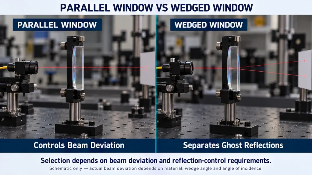
A window with two nonparallel surfaces behaves like a weak prism and changes the direction of the transmitted beam. The amount of angular deviation depends on the wedge and refractive index.
Parallelism may be specified in arcminutes, arcseconds or another angular unit. Select the tolerance according to the permitted beam deviation.
Some systems intentionally require a wedged window. A controlled wedge can move ghost reflections away from a detector or prevent unwanted etalon effects. If wedge direction matters, it should be identified on the drawing.
8. Define the Clear Aperture
The clear aperture is the usable area over which the optical specifications apply.
It may be stated as:
- A specific diameter
- A defined rectangular area
- A percentage of the outside dimension
For example, a drawing may require a clear aperture greater than 90% of the diameter.
The clear aperture normally excludes the bevel and a small edge zone that cannot be polished or inspected in the same way as the central area. If the coated area differs from the optical clear aperture, specify both dimensions separately.
9. Specify the Optical Coating
Uncoated optical surfaces produce Fresnel reflection. An antireflection coating can improve transmission and reduce ghost reflections.
A complete coating requirement should include:
- Operating wavelength or wavelength band
- Angle of incidence
- Polarization when relevant
- Average or maximum reflectance
- Minimum transmission when required
- Number of coated surfaces
- Environmental durability
- Laser damage requirement when applicable
A measurable requirement might be:
Ravg < 0.5% per surface from 450–650 nm at 0° AOI
Here, Ravg means average reflectance across the stated wavelength band. If the limit must be met at every wavelength, specify a maximum value such as Rmax instead. Average reflectance, maximum reflectance and minimum transmission are different requirements and should not be used interchangeably.
Do not specify only “AR coated.” A coating designed for normal incidence may perform differently when the window is tilted.
If the two surfaces require different coatings, identify them as Side 1 and Side 2 on the drawing.
10. Consider the Operating Environment
The window must provide both optical performance and suitable environmental durability.
Tell the supplier about:
- Minimum and maximum temperature
- Temperature cycling
- Humidity
- Vacuum or pressure difference
- Outdoor exposure
- Rain and dust
- Abrasion
- Chemical exposure
- Cleaning method
- Shock and vibration
- Mounting and sealing method
For a pressure window, the required diameter, unsupported aperture, thickness, mounting method and safety factor should be evaluated together. Material strength alone is not sufficient to confirm a safe design.
11. State Quantity and Inspection Requirements
Include the prototype quantity, production quantity and expected repeat demand.
Also state whether you require:
- Standard inspection
- Dimensional inspection report
- Material certificate
- Coating measurement
- Interferometric report
- Certificate of conformance
- First article inspection
- Special packaging
Additional testing and documentation may affect price and delivery time, so these requirements should be included in the original RFQ.
Common Optical Window Specification Mistakes
Selecting Material Only by Transmission Range
Published transmission ranges are general material-level references. Finished performance also depends on thickness, surface condition, temperature and coating.
Confusing Surface Quality With Flatness
Surface quality controls scratches and digs. Flatness controls the shape of the polished surface.
Requesting Extremely Tight Parallelism Without Need
Tight parallelism can increase manufacturing and inspection costs. Base the requirement on allowable beam deviation.
Writing Only “AR Coated”
Always state the wavelength band, angle of incidence and required optical performance.
Ignoring the Mounting Environment
A window can meet its optical requirements and still fail because of mounting stress, pressure, thermal expansion or improper sealing.
Frequently Asked Questions
Does Every Optical Window Need an AR Coating?
No. An uncoated window may be suitable when reflection loss is acceptable or maximum surface durability is preferred. AR coatings are commonly used when transmission and reflection control are important.
What Surface Quality Is Suitable for a Standard Window?
A 60-40 specification is common for many general optical applications, but the correct value depends on imaging, laser and cosmetic requirements.
Is Flatness the Same as Transmitted Wavefront?
No. Surface flatness describes an individual surface. Transmitted wavefront includes the combined effects of both surfaces, material homogeneity and internal stress.
Should an Optical Window Be Parallel or Wedged?
Parallel windows are common when beam deviation must be minimized. Wedged windows may be preferred when ghost reflections or interference effects must be separated.
What Information Is Needed for a Quotation?
Provide the application, wavelength, material, dimensions, tolerances, surface quality, flatness, parallelism, clear aperture, coating, quantity and inspection requirements.
Custom Optical Windows from Chenyu Optics
Chenyu Optics supports drawing-based production of custom optical windows for imaging, laser, sensing, industrial and scientific systems.
Available requirements can be reviewed according to:
- Optical material and grade
- Circular, rectangular or custom shape
- Diameter and thickness
- Dimensional tolerances
- Surface quality
- Surface flatness
- Parallelism or wedge
- Clear aperture
- Transmitted wavefront
- AR or application-specific coating
- Prototype and production quantities
- Inspection and packaging requirements
Final specifications should be confirmed according to the customer drawing, application, manufacturing capability and available inspection method.
Need Help Specifying an Optical Window?
Send Chenyu Optics your wavelength, material, dimensions, coating requirements, operating environment and expected quantity. If some tolerances have not been determined, provide the required system performance for review.